


Analog gas sensors send out a continuous voltage or amperage proportional to the gas level. Digital gas sensors send and receive strings of characters that can be read by a micro-processor or a computer.
The image above is a COZIR CO2 sensor connected to a Arduino Mega board via RS-232.
Table of Contents
ADC Converters Enable Digital Gas Sensors
Which is Best for Your Application?
Introduction
Ask the average person what’s the difference between analog and digital and they’ll say “Analog is old – digital is new.” Chances are they learned this watching ads for digital TVs, DVDs or computers.
And they are right: analog gas sensors have been around longer than digital gas sensors. But both still have an important part to play when measuring gases like oxygen, carbon dioxide, methane and more.
All Gas Sensors are Analog
While many scientists had worked on gas detection technology, one of the earliest and most successful was Mr. Naoyoshi Taguchi in Japan. Throughout the 1960s he developed and commercialized an electrochemical gas sensor that would output an analog electrical signal proportional to the amount of propane in air. Devices based on this technology are still referred to as "TGS" (Taguchi Gas Sensors).
The advantage of an analog electrochemical gas sensor is that in general, as the level of the gas increases, the electrical output of the sensor – amperage or voltage – also increases. Once the sensor is calibrated, the signal can be used to drive an ammeter or voltmeter which shows on a dial gauge the amount of gas present.
Note that even modern non-dispersive infrared (NDIR) gas sensors are internally analog gas sensors. NDIR is the infrared absorption by gas molecules in a specific spectrum measured by a special photo sensor. The amount of infrared light that is detected is read as either milliamperes (mA) or microvolts (mV), then boosted with an amplifier circuit. In order to read this analog signal, an analog-to-digital (ADC, A/D or A-to-D) converter is added to the sensor’s circuitry.
In other words, all gas sensors are analog. It is the addition of an on-board analog-to-digital converter that makes a digital gas sensor possible.
ADC Converters Enable Digital Gas Sensors
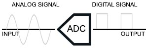
An analog to digital converter changes an analog voltage or current from the sensor to a digital output that represents the gas level. While the science of converting an analog signal to a digital one is complex, the useful output is a string of numbers or letters representing the gas level that can be easily read by a micro-processor or a computer.
On digital gas sensors, the ADC converter and logic is incorporated on a microchip on the printed circuit board with the sensor. The close proximity of the ADC chip to the analog gas sensor on the board makes it possible to create gas sensor applications with a fast response time. However, the additional electronics is one of the reasons digital gas sensor systems are more expensive than analog gas sensors.
Analog Signal Output
Analog gas sensors output one or more of three industry standards: 4-20 milli-amperes, 0-10 volts DC or 0-3 volts DC.
4-20mA Analog
4-20mA is the industry standard for process control applications where the values of 4 and 20 milli-amperes represent 0 and 100% gas. The signal from the sensor is carried to process instrumentation to proportional integral derivative (PID) controllers, SCADA systems, and programmable logic controllers (PLCs). The advantage of 4-20mA is that a 0mA output signifies a sensor fault (no signal).
0-10VDC Analog
0-10v or 0-10VDC is one of the simplest control signaling systems where 0 volts represents no gas and 10 volts represents 100% gas level from the sensor. The 0-10 volt standard is primarily used in the HVAC industry. The primary disadvantage is that 0v can be caused by either no gas or a bad sensor, and because of the higher voltage needed, the analog sensor must have additional power and circuitry.
0-3VDC Analog
0-3VDC is similar to 0-10VDC, it has the same disadvantages, but is used in cases where lower power input and output is required.
Digital Signal Output
RS-232 Serial
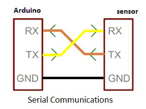
The most common digital signal output is RS-232, the industry standard for serial data input and output. RS-232 transmits positive and negative voltages across 2 wires that are converted to binary 0’s and 1’s. The transmit data and receive data wires (Tx and Rx) plus a ground wire are all that are needed to send and receive a digital signal from a sensor.
The advantage of being able to both receive and transmit data means that the sensor can be remotely configured or calibrated from a micro-processor or a PC. The disadvantage is that because the data is transmitted “serially” point-to-point. Only one electronic device can talk to another over a serial cable.
RS-232 was originally designed for telecommunications systems and is used in computer COM ports. In modern personal computers, USB has displaced RS-232, so an external USB to RS-232 converter is often used. However, because RS-232 is an industry standard it is still often used where a short-range, point-to-point, low-speed wired data connection is acceptable.
RS-485
RS-485 is an industry standard that allows multiple sensors (called slaves) to communicate with a supervisory computer (master) over a single set of 3 wires. By default, Modbus can handle up to 32 sensors on a single cable, but with additional hardware signal repeaters it can handle up to 256. The advantage of Modbus over RS-232 is that the maximum distance between the master and the last slave on the cable can be 1,200 meters.
Learn more about RS-485 communication with GasLab sensors here.
I2C
Inter-Integrated Circuit, or I2C is a digital communications method many sensors now include. Intended to reduce wiring complexity over short distances, it is a simple synchronous scheme the allow for multiple devices to share a signal over 2 wires like RS-232. The wires are referred to as SCL (clock) and SDA (data).
With I2C, you can connect multiple slaves to a single master or you can have multiple masters controlling single or multiple slaves. A useful example of this would be to have sensor data sent to both a memory card to log data and an LCD for real-time display.
Modbus
Modbus is a type of serial communication protocol often included in the logic of digital gas sensors. It is an open-source standard for connecting industrial electronic devices.
Modbus is not a digital output. Instead, it acts as a wrapper around other kinds of digital data like RS-485, RS-232 Serial or TCP Ethernet. By sending and receiving digital signals encoded with Modbus rules and commands, multiple sensors (called slaves) can be controlled by a supervisory computer (master) over a single set of wires or on the same network.
Which is Best for Your Application?
Before you select a gas sensor it is important to know which analog or digital signal outputs it supports. Most electrochemical sensors only output a 4-20 mA signal, while more sophisticated sensors output both analog and digital outputs.
In our experience, sensors that output RS-232 serial output have the most flexibility as they can communicate with PCs, over USB and with Raspberry Pi or Arduino micro-processors. Modbus and RS-485 may be included with the sensor output logic, or can be added later with inexpensive connectors.

